
pfSense Installation
Click on  on the top right of the screen
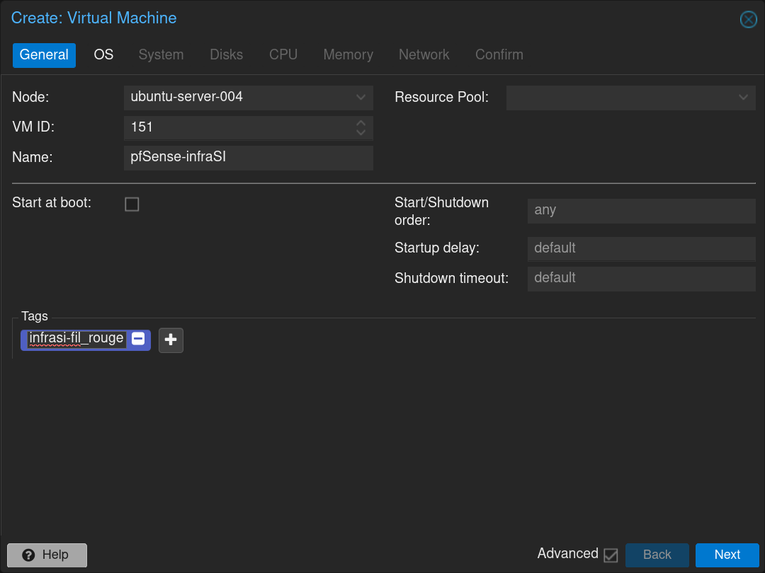
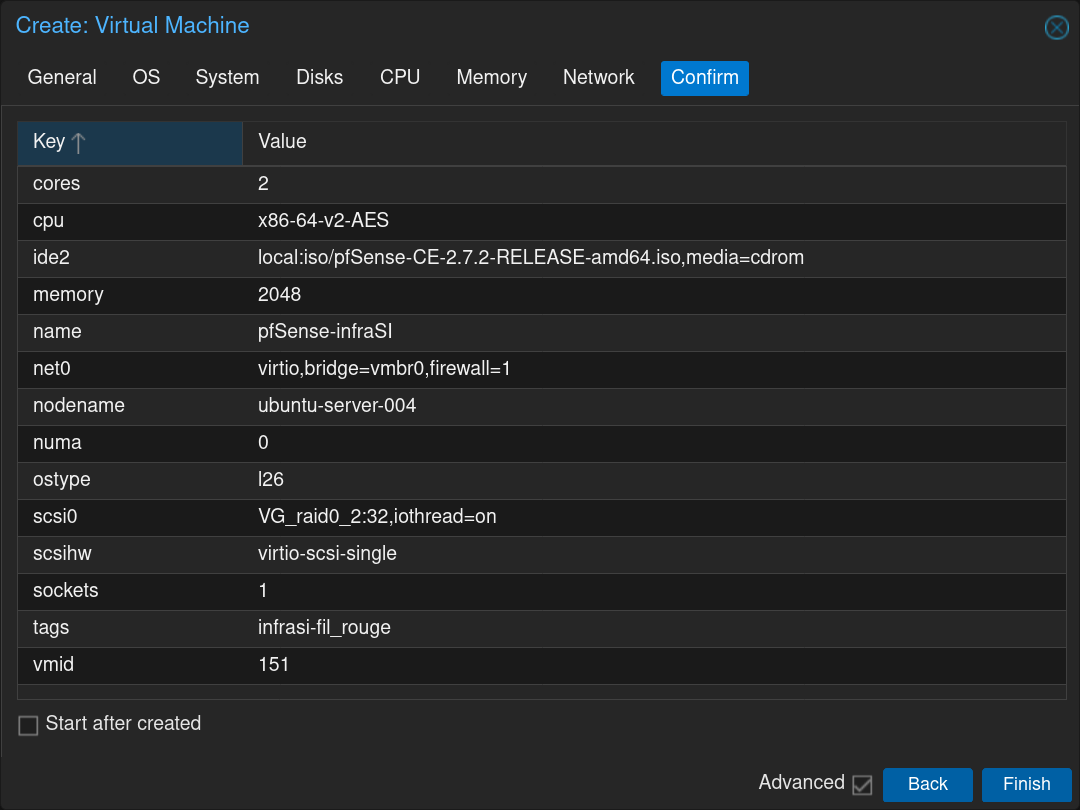
Fill the form with the name of the VM pfSense-infraSI and click Next
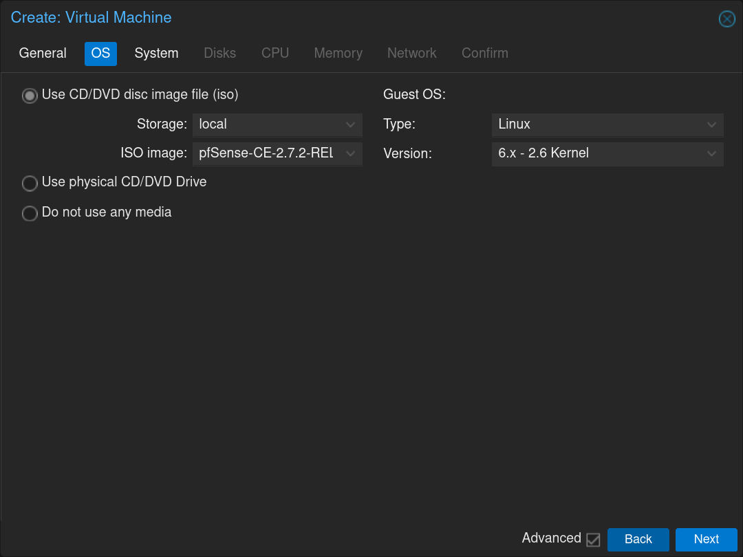
Select the pfSense .iso image and click Next
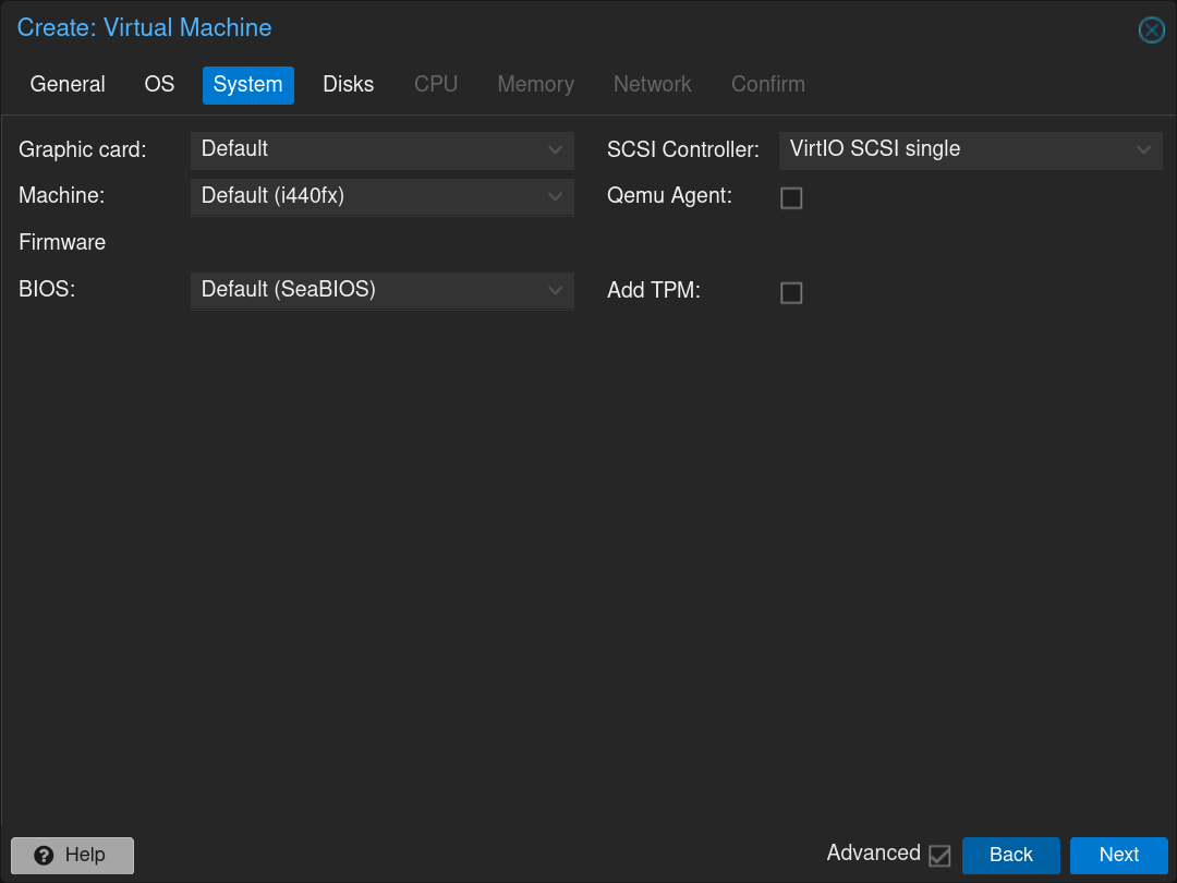
Click Next
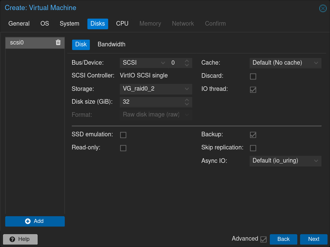
Select the disk in which install it and the size of the partition 32GiB and click Next
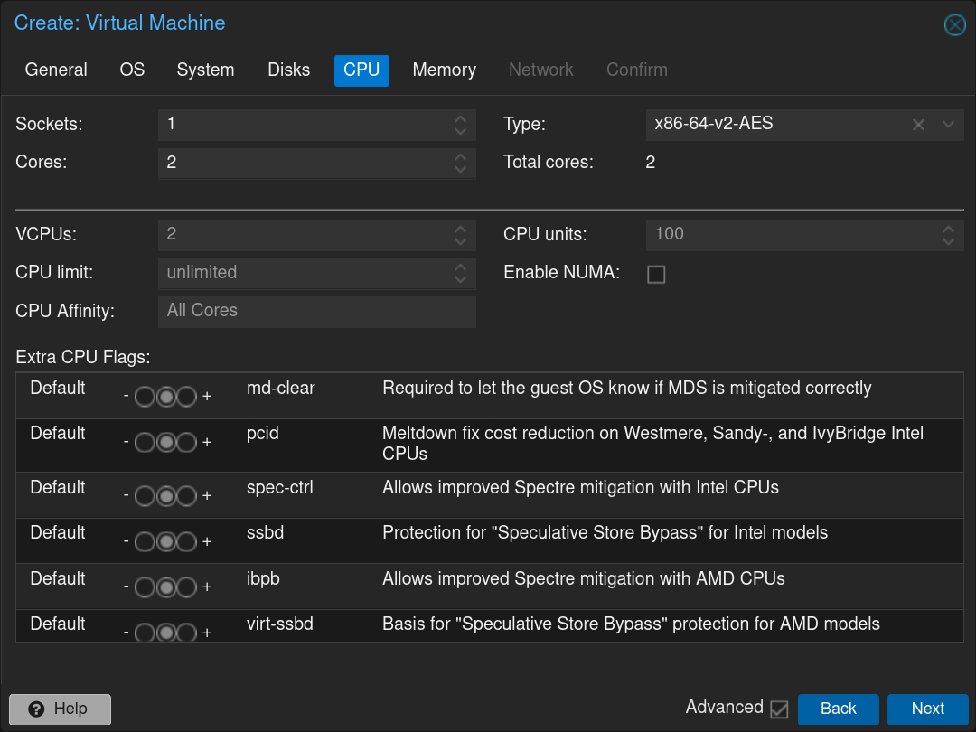
Select the number of CPUs to allocate: 1 CPU with 2 cores and click Next
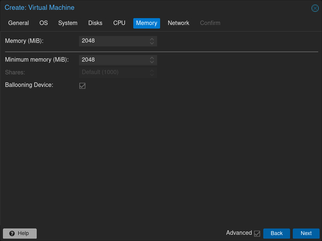
Select the RAM to allocate: 2048MB and click Next
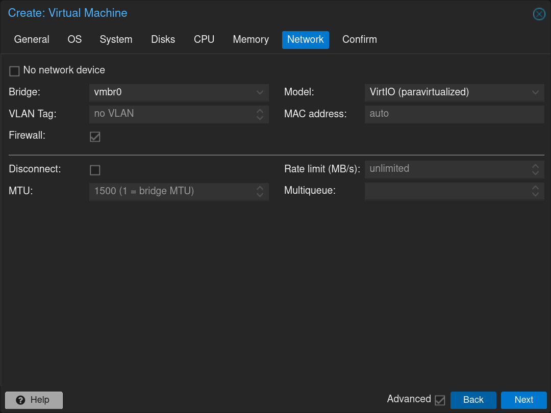
Select the first network interface: vmbr0 (WAN interface) and click Next
Confirm the creation of the pfSense VM
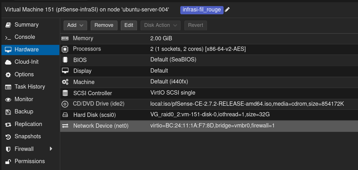
Click on the newly created VM and then click on the tab Hardware
Click on Add and then on Network Device and select the Bridge vmbr4 dedicated to the DMZ network then click on the Add button
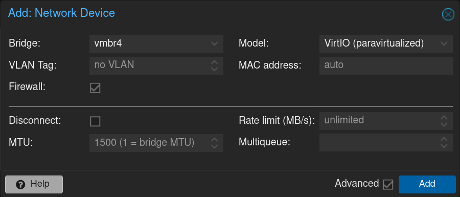
Repeat the process with the Bridge vmbr5 dedicated to the LAN network with the VLANs

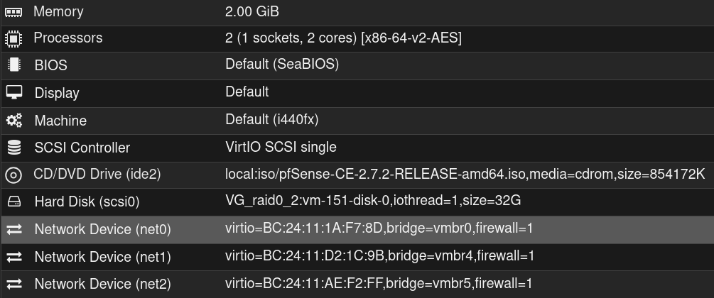
Here is the result
Click on  and then on
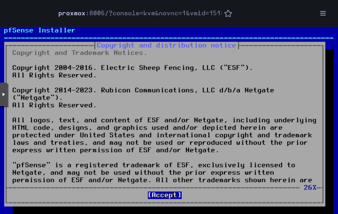
Then the VM will boot and the installer will start. Accept the license and rights
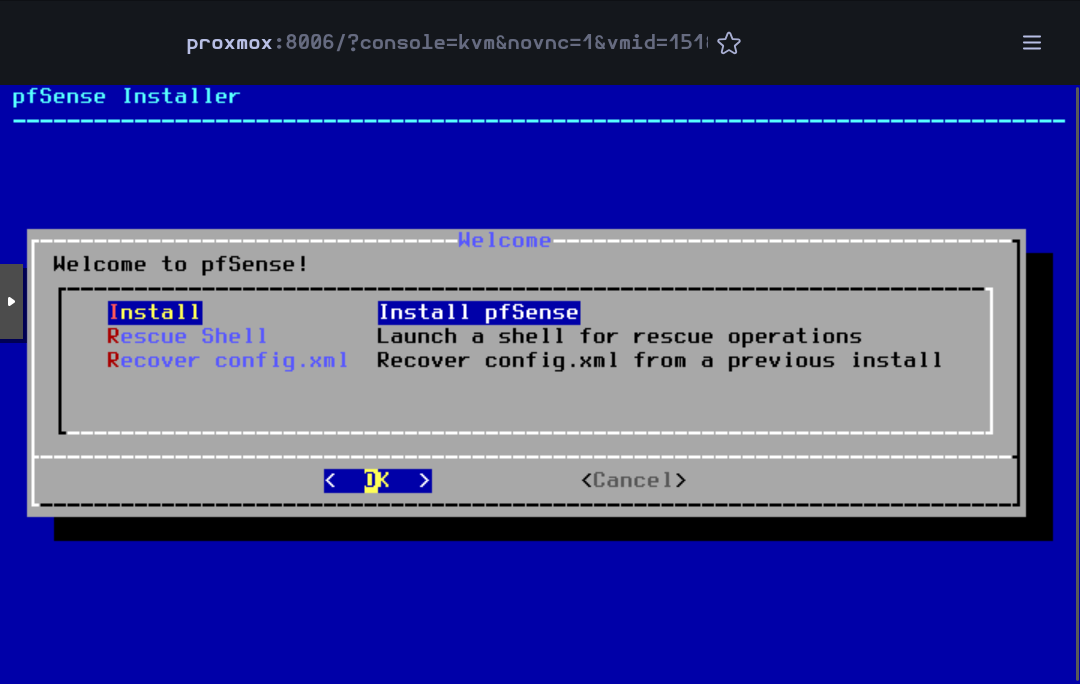
Press on Enter to begin the installation
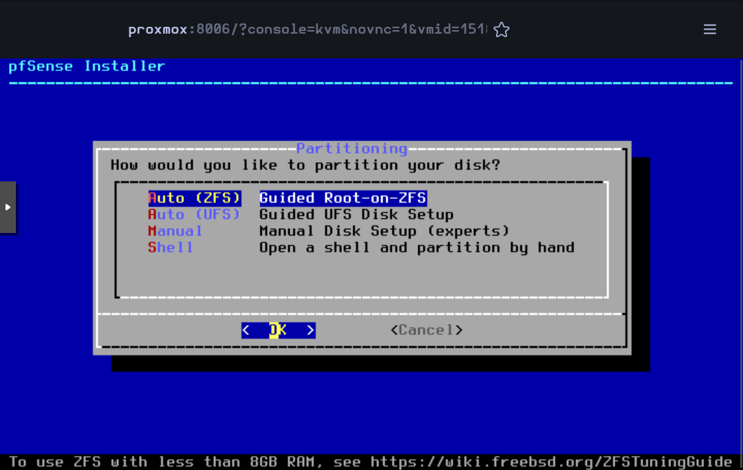
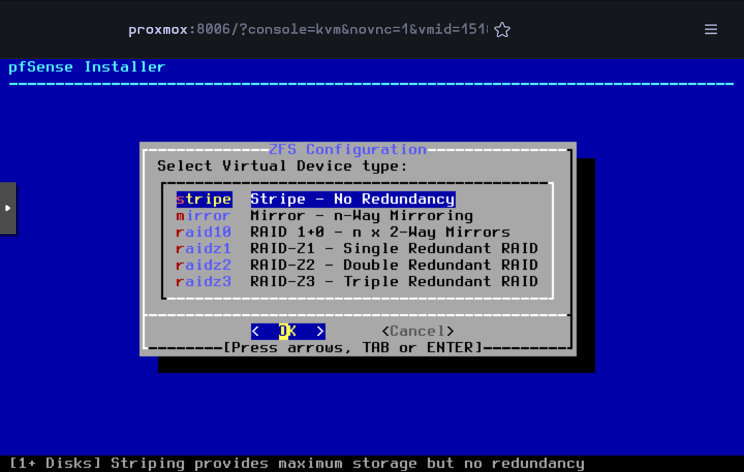
Accept the default partitioning option Auto (ZFS)
Press Enter to begin the installation
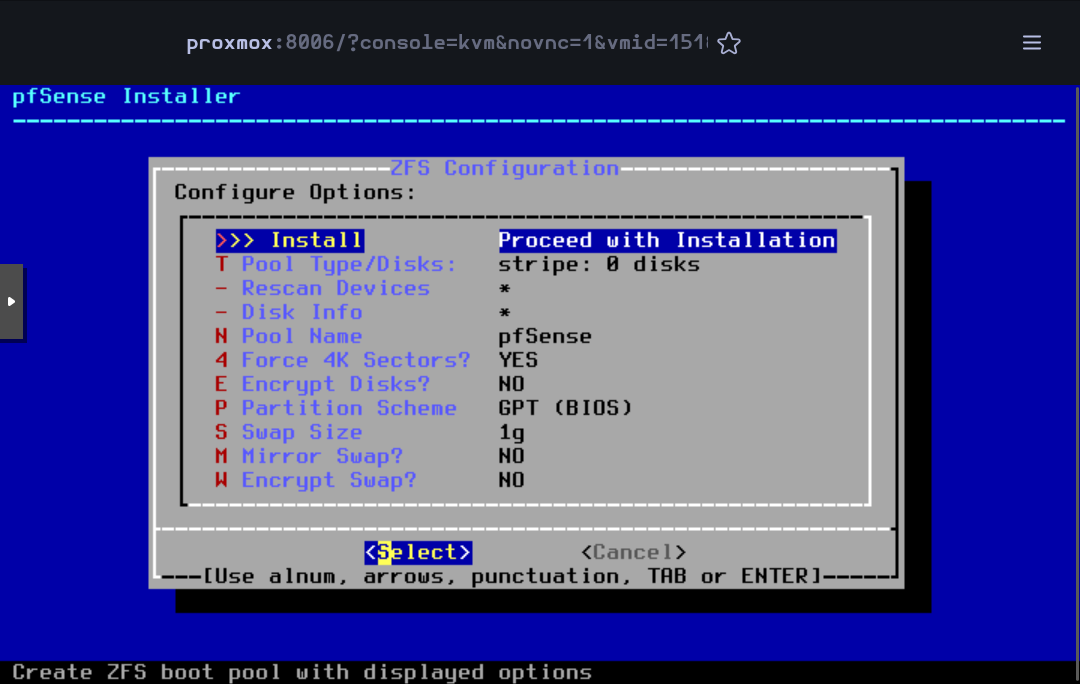
Press Enter to accept the default Stripe mode
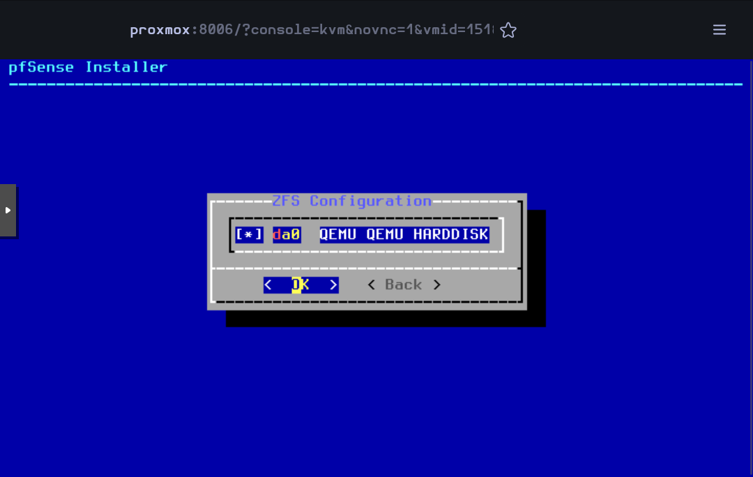
Press Space to select the disk and then Enter to go on
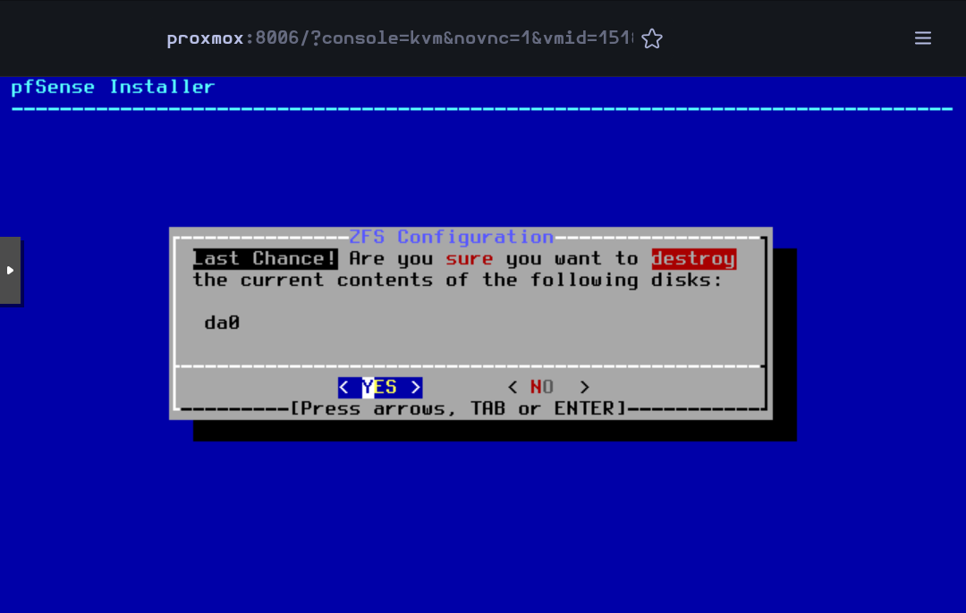
Select Yes and press Enter
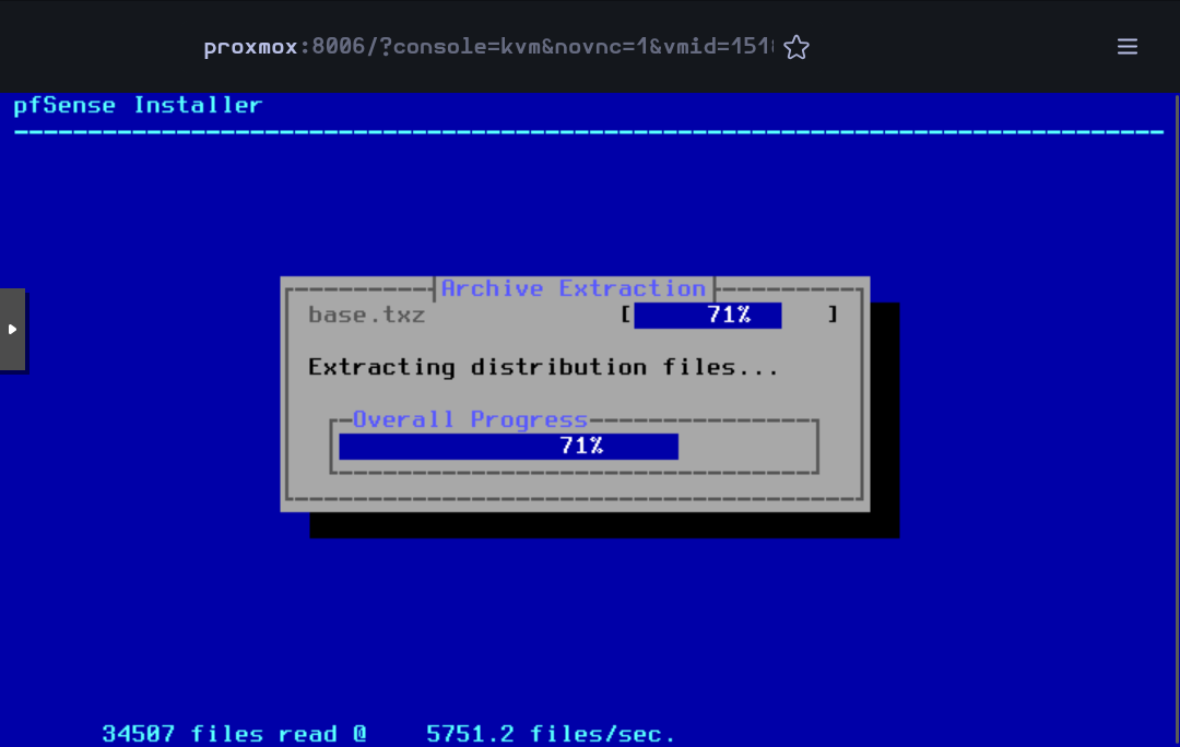
Then, the installation will begin
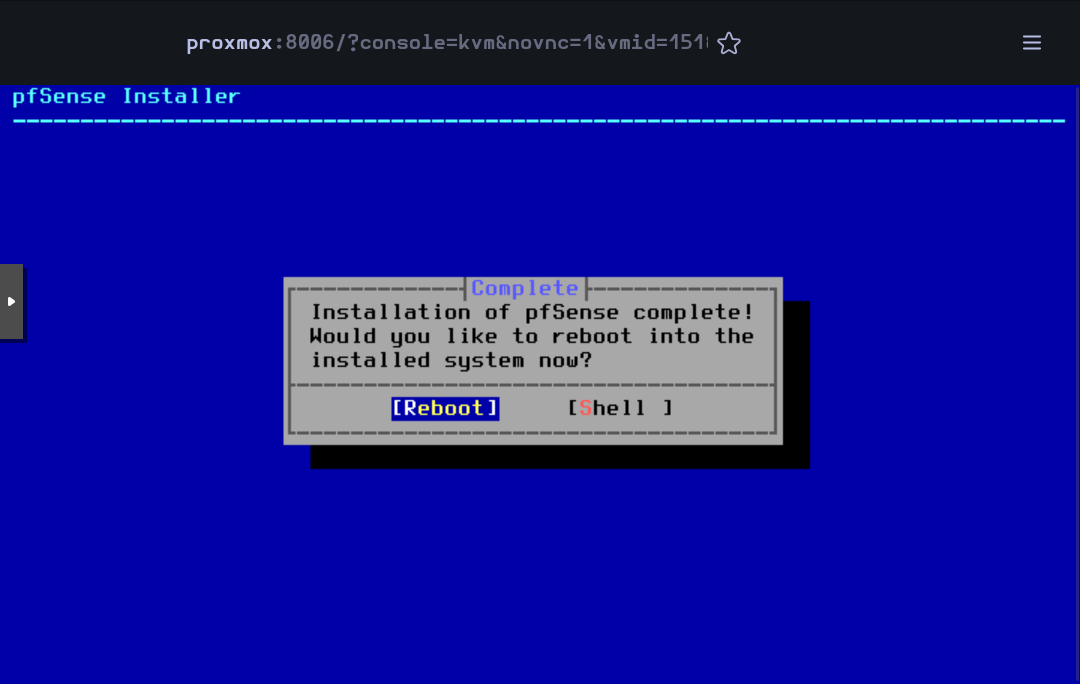
When finished, accept to reboot the VM
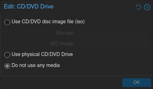
While rebooting, you can remove the .iso image editing the CD/DVD Drive in the Hardware section
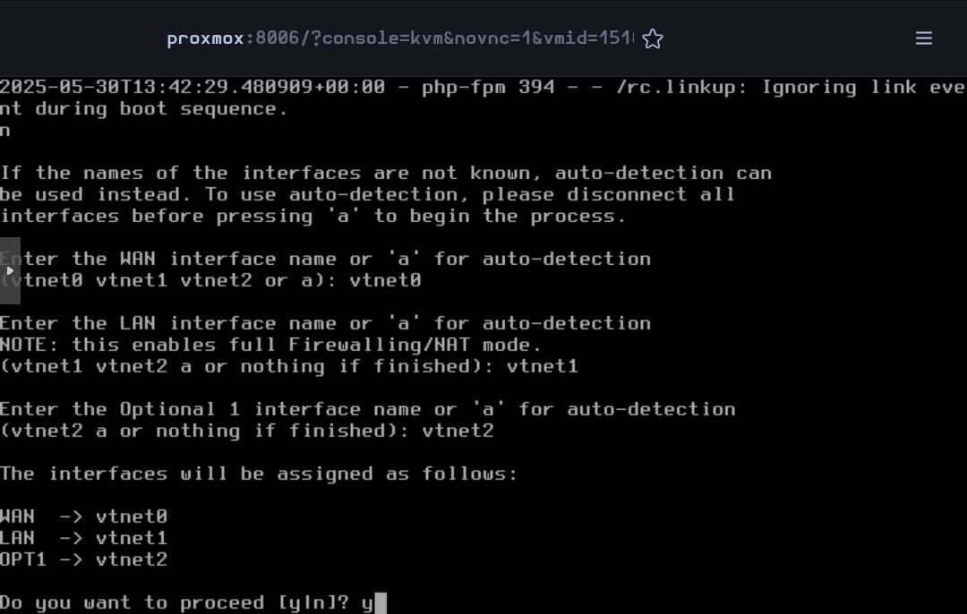
When the VM has rebooted, some basic configuration will be done in the command line interface.
For the VLANs, type n for the moment (they will be created in the web interface)
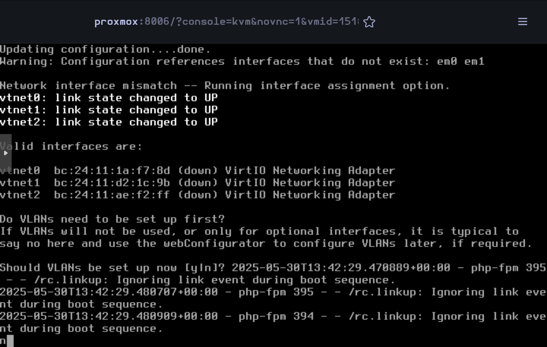
Type vtnet0 for the WAN interface, vtnet1 for the LAN and vtnet2 for the OPT1
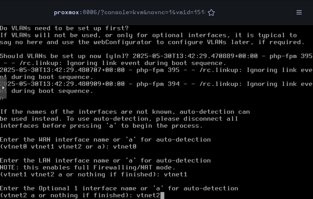
Confirm the network interface configuration
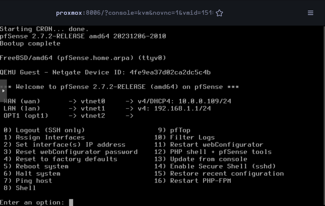
Now the installation is complete. The rest of the configuration will be done on the web interface.
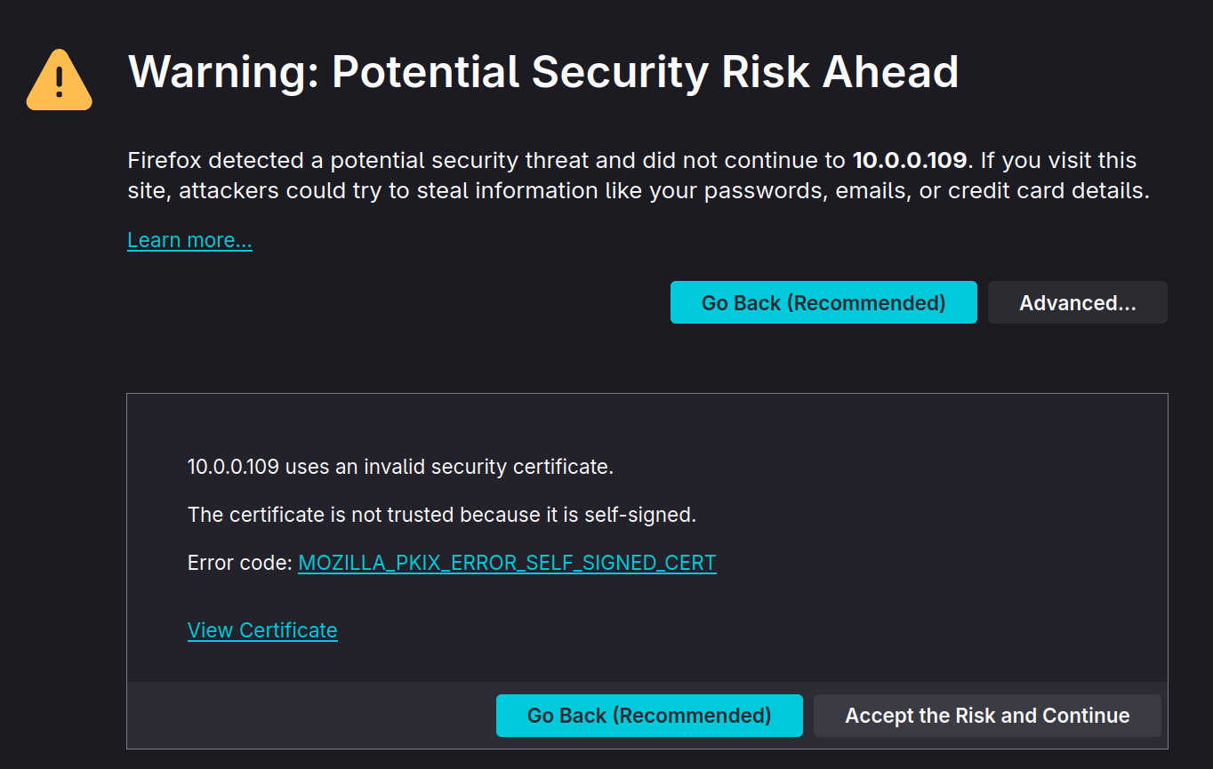
Open the browser and go to pfSense's web interface. Accept the warning to continue.
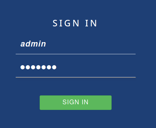
Then log in the web configurator with the default credentials (admin - pfsense)
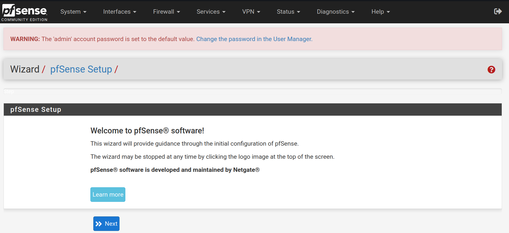
The first thing to do when signing in the web configurator is to follow a setup wizard. Click on Next
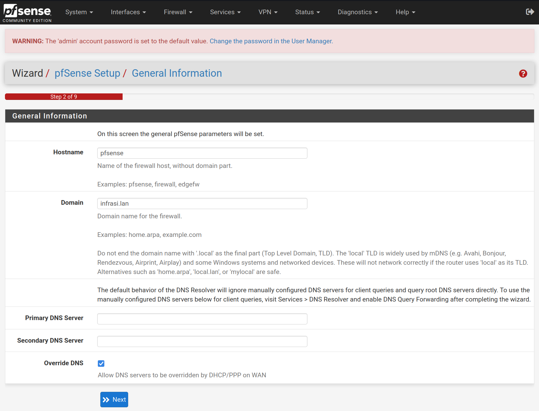
Type pfsense in lowercase for the hostname and infrasi.lan for the domain name, then click on Next
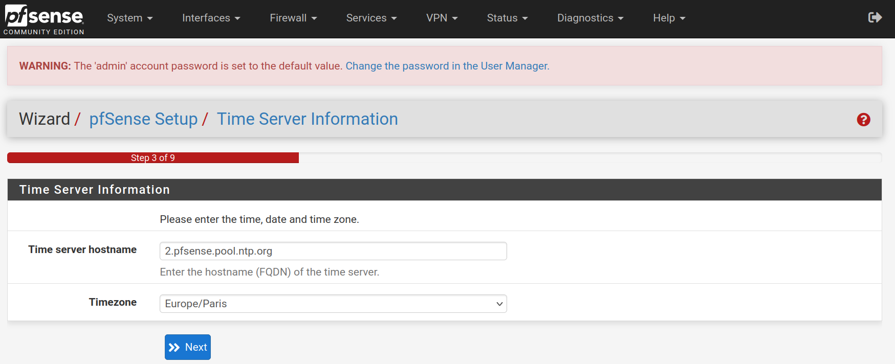
Select the timezone Europe/Paris for the NTP configuration
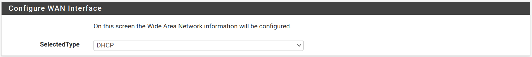
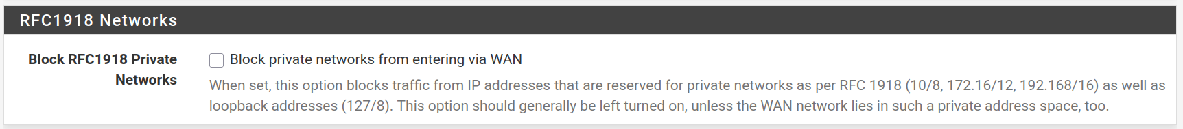
Keep the WAN interface set on DHCP and uncheck the Block RFC1918 Private Networks and Block bogon networks rules and click on Next

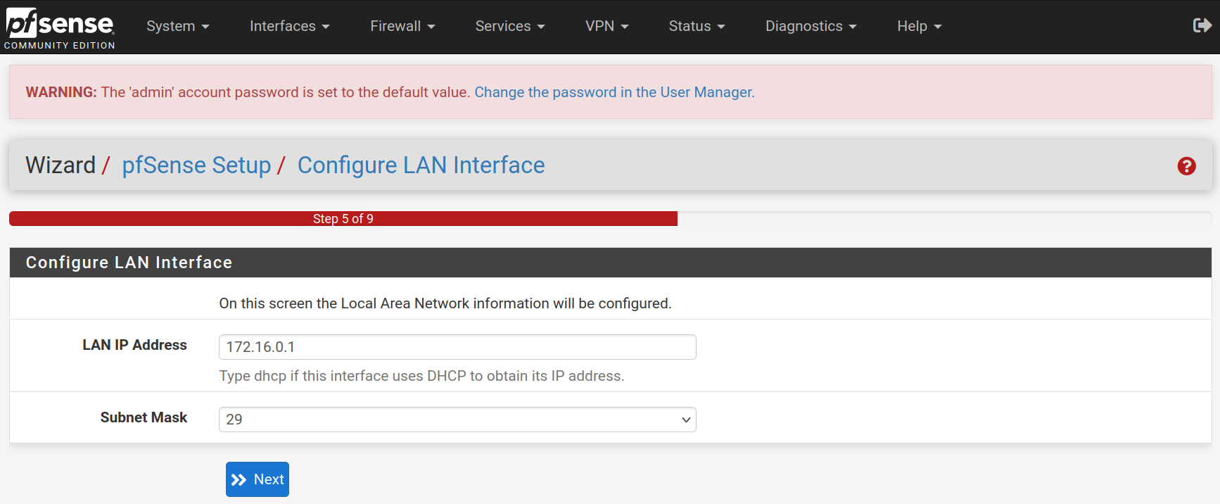
For the LAN interface, type the static IP address 172.16.0.1 and the subnet mask 29 to allow 6 hosts for the moment. It will be easily upscaled afterwards. Then click on Next
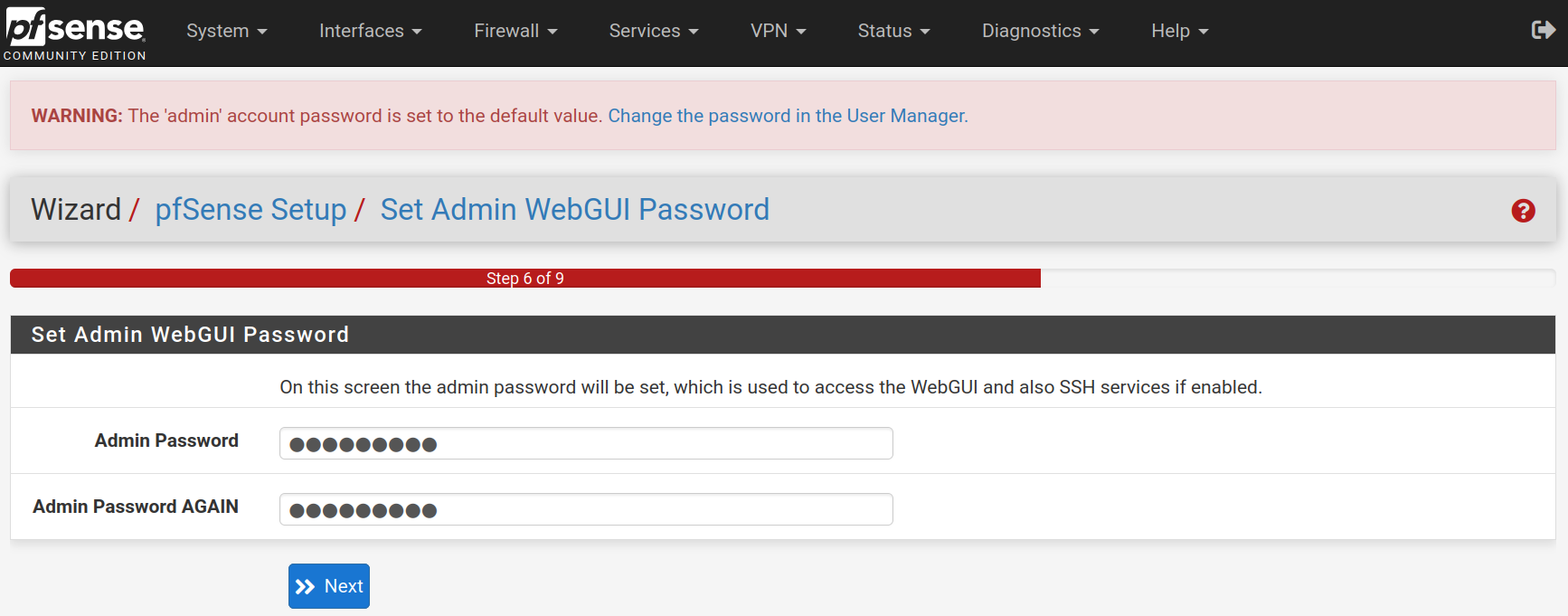
Type a new password and confirm it. Click on Next
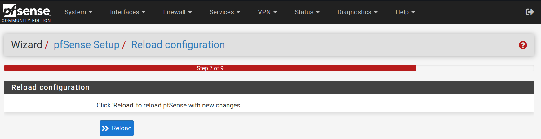
Click on Reload to accept and apply the new configurations.
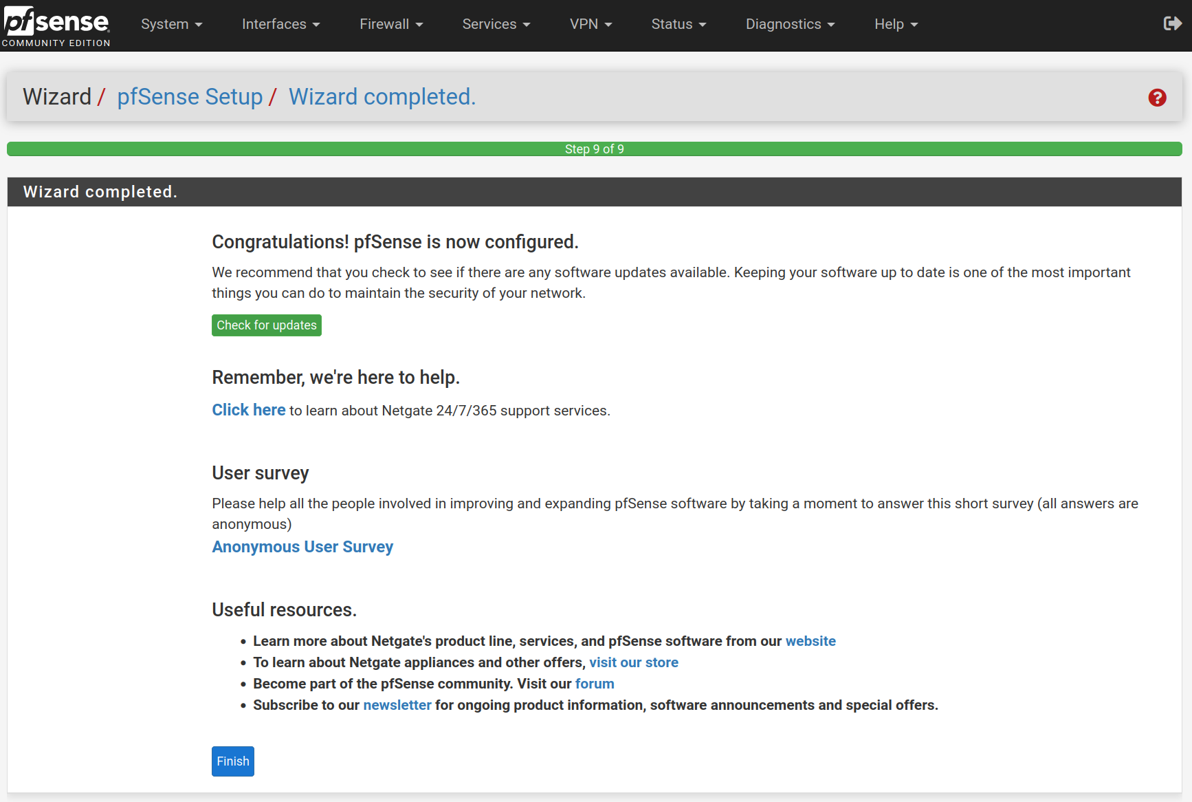
Click on Finish
Accept the license and right.
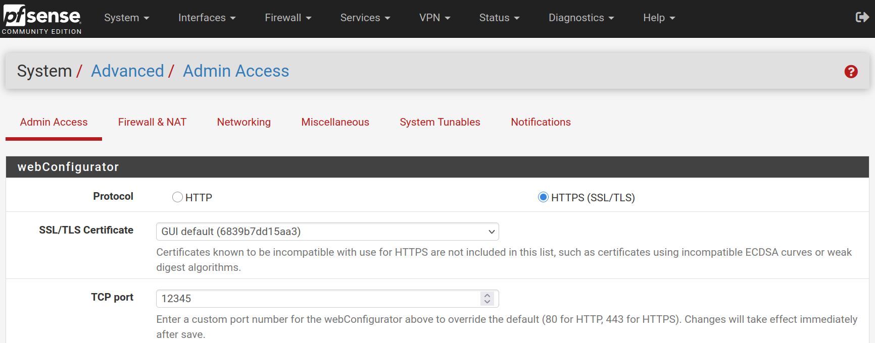
Go to System > Advanced and change the web configurator port to 12345 to free the HTTPS port.
If you want, you can go to System > General Setup to change the CSS theme of the web configurator

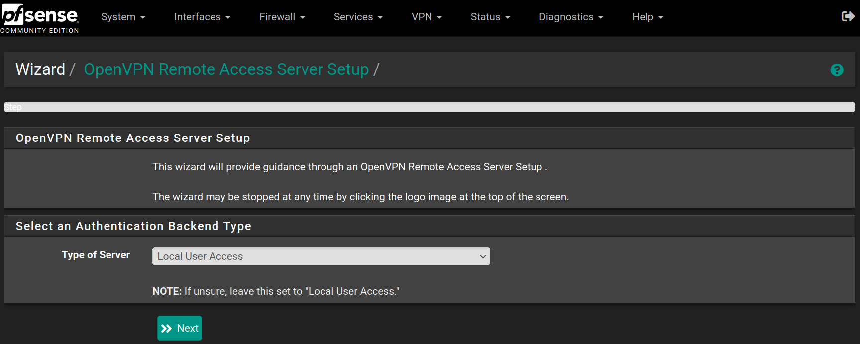
Go to VPN > OpenVPN in the Wizard tab and click Next
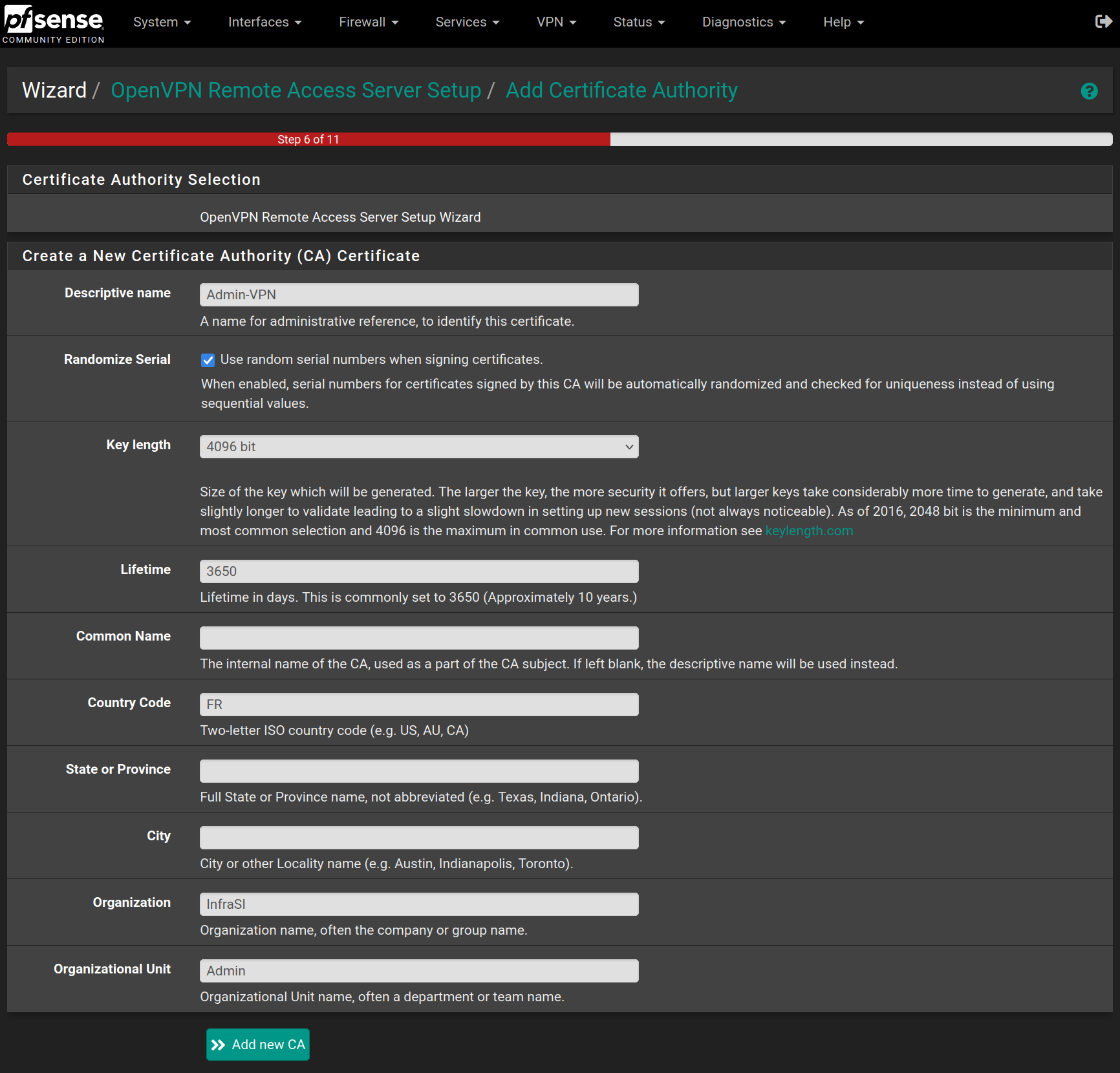
Fill the form with the following values and click on Add new CA
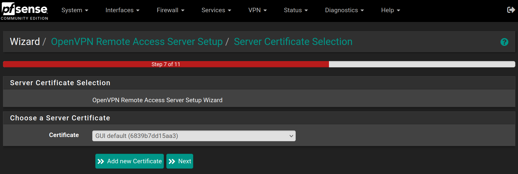
Then click on Add new Certificate
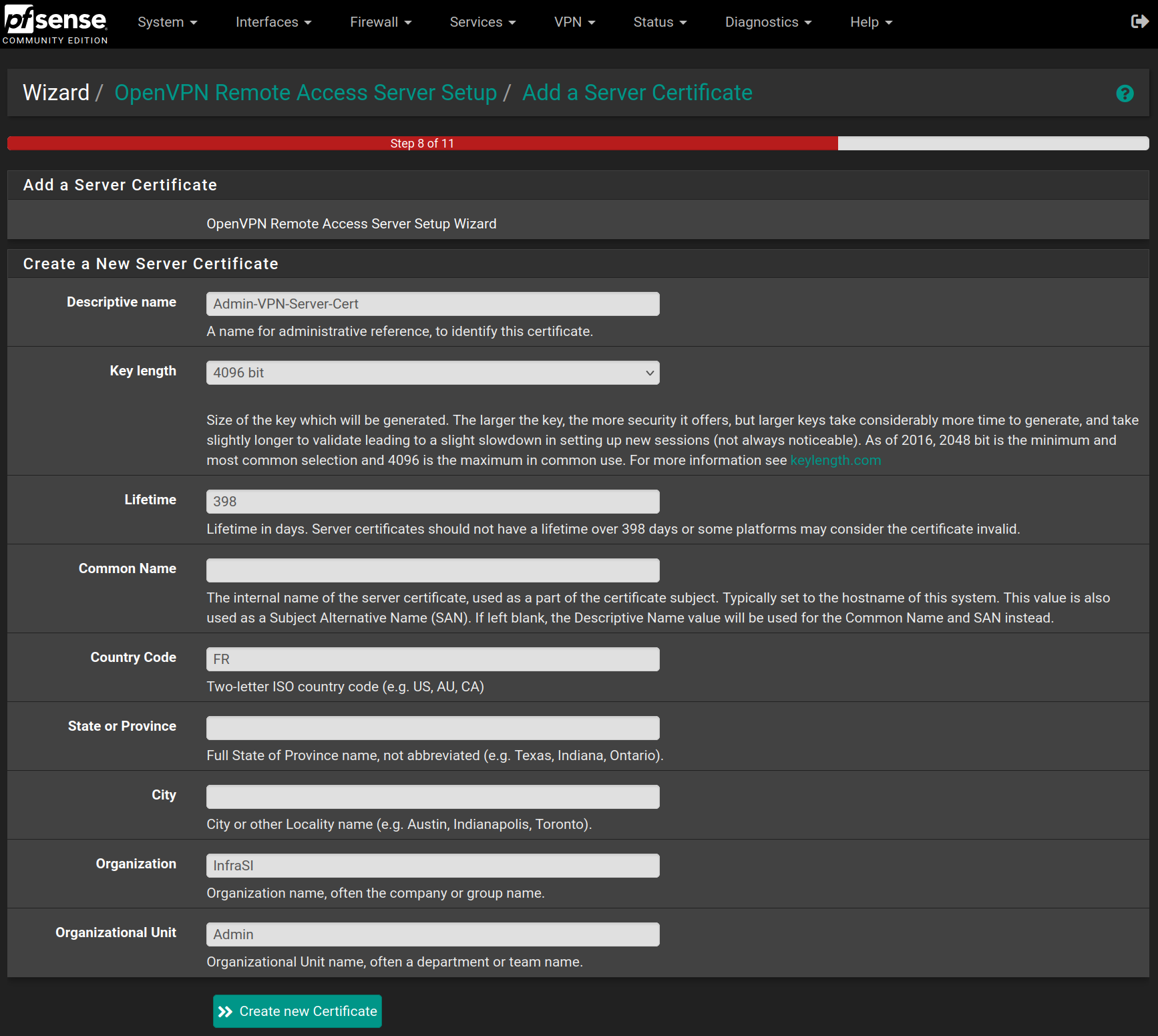
Fill the form with the following values and click on Create new Certificate
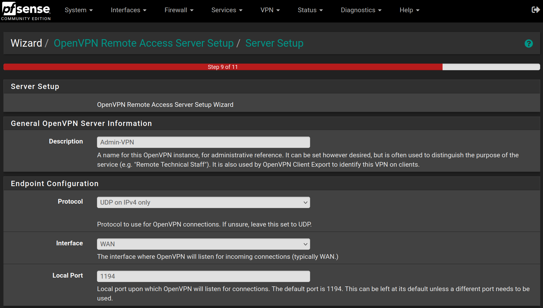
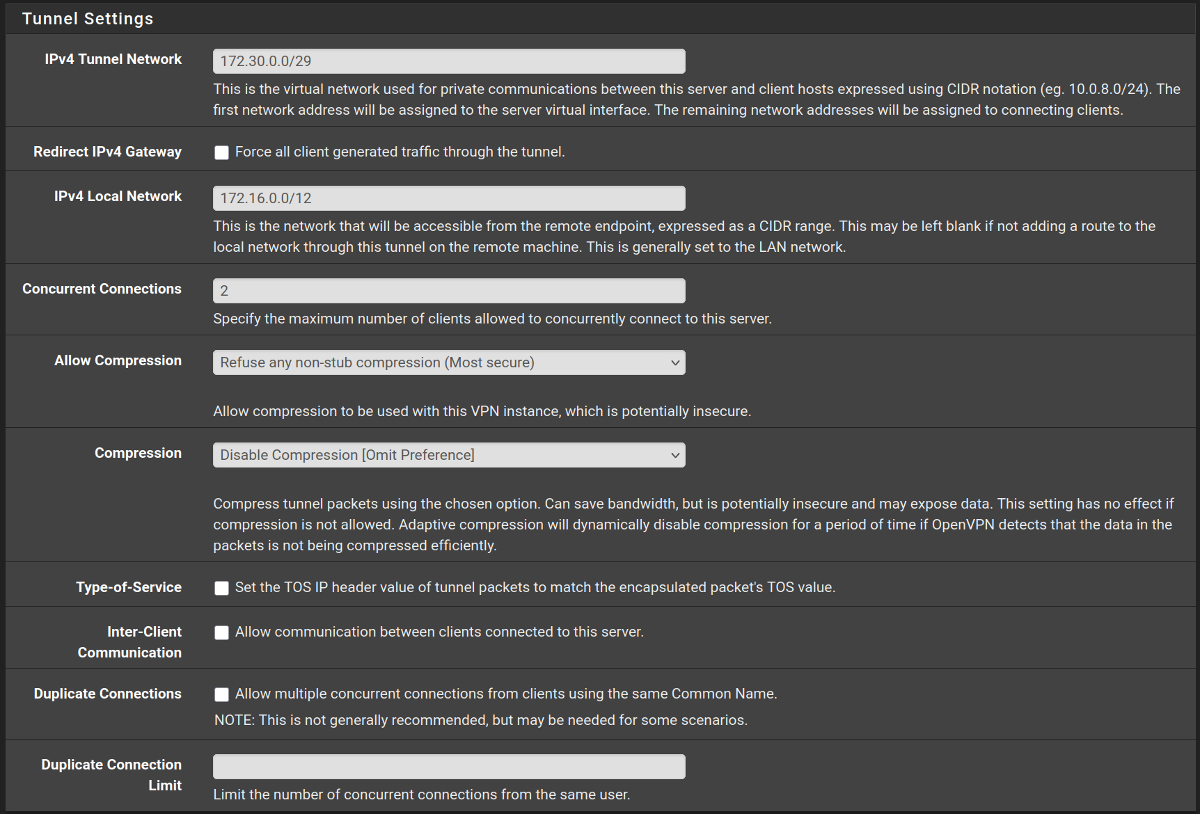
Fill the form with the following values and click on Next

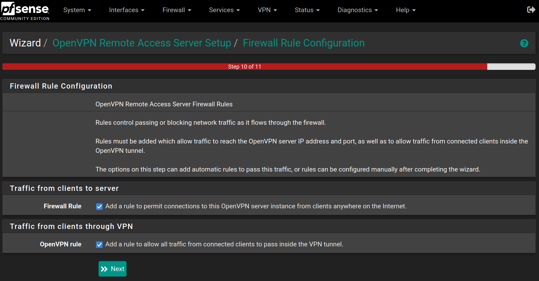
Check the two rules to allow access from wherever to pass through the VPN tunnel and click on Next
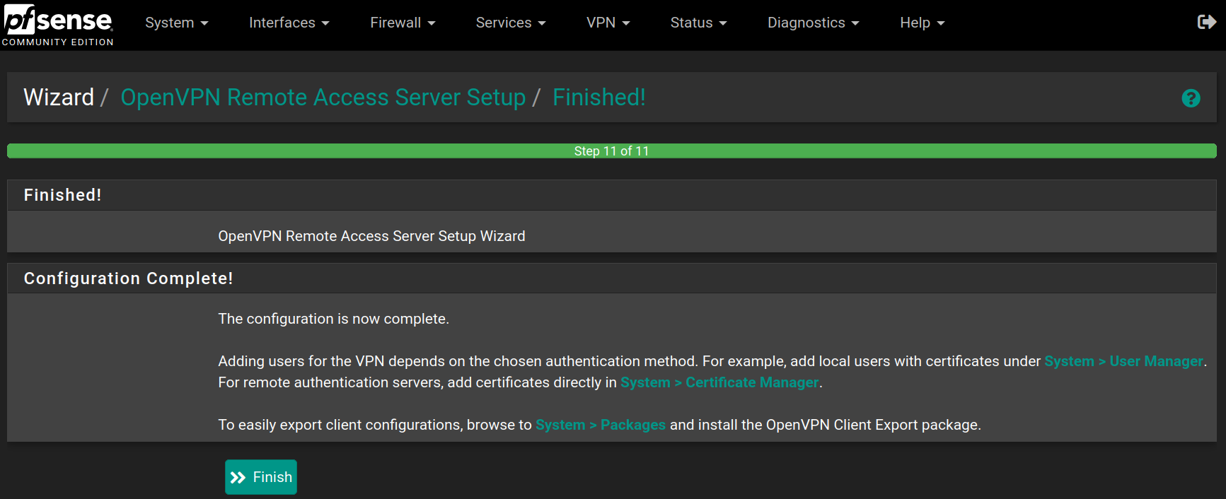
Click on Finish to save and apply the OpenVPN Server
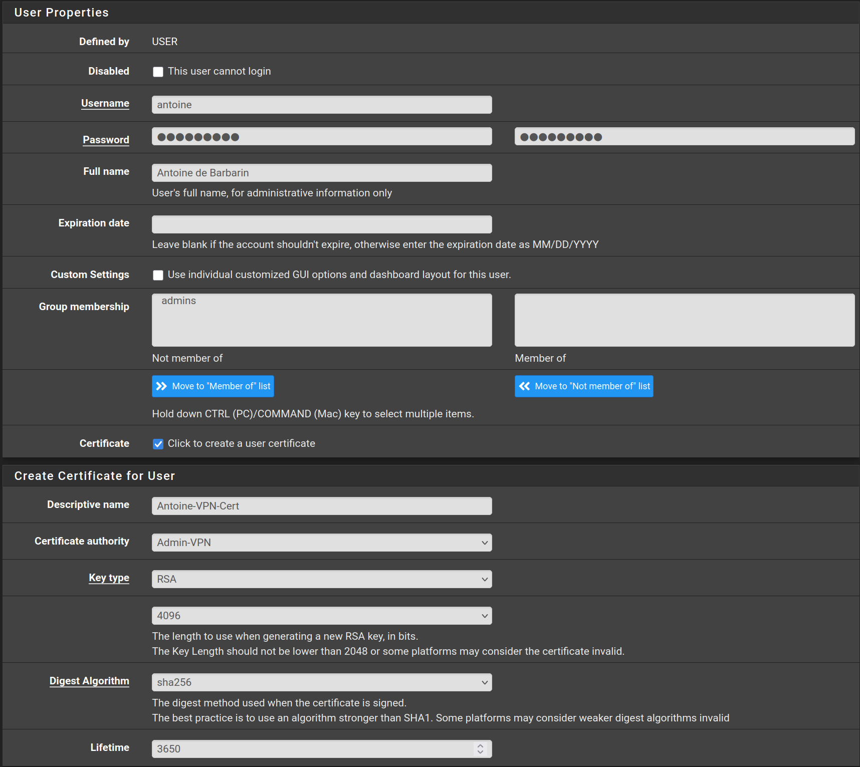
Go to System > User Manager and click on Add
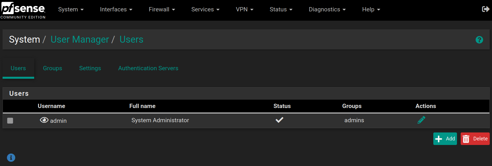
Fill the form with the following values and click on Save
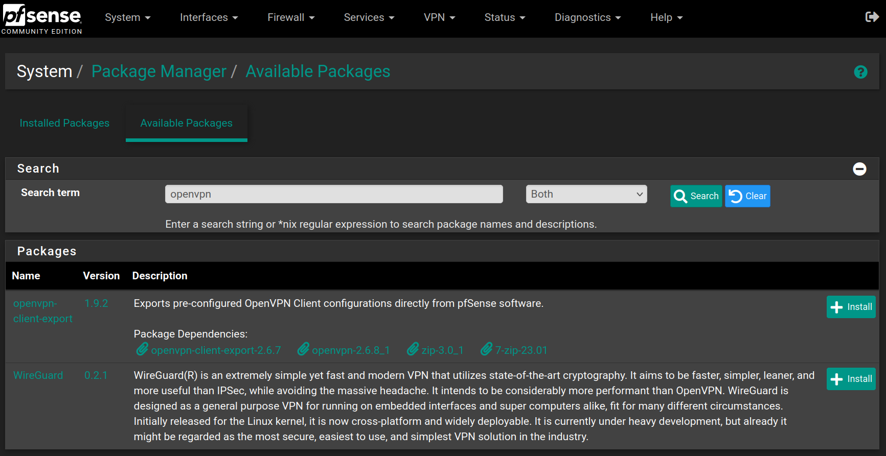
Go to System > Package Manager > Available Packages and search for openvpn, then on the package named openvpn-client-export click on Install and Confirm
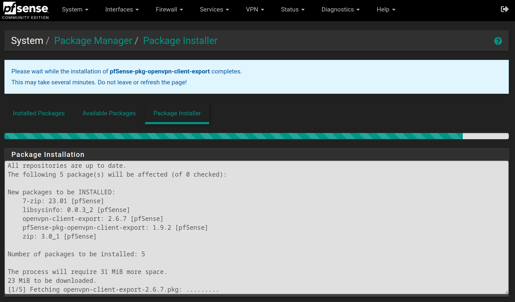
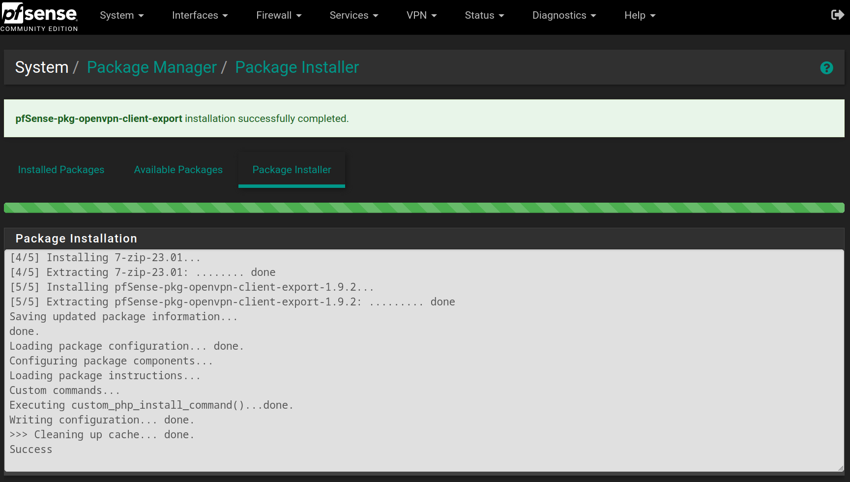
Wait for the installation to finish
Go to VPN > OpenVPN > Client Export and at the bottom of the page, you can download the exact configuration to connect to the Admin-VPN.
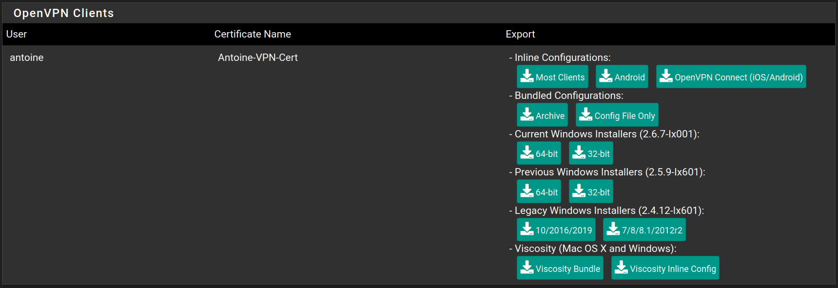
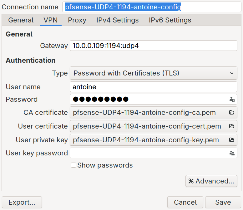
After downloading the configuration (I chose Inline Configuration > Most Clients), you can access it.
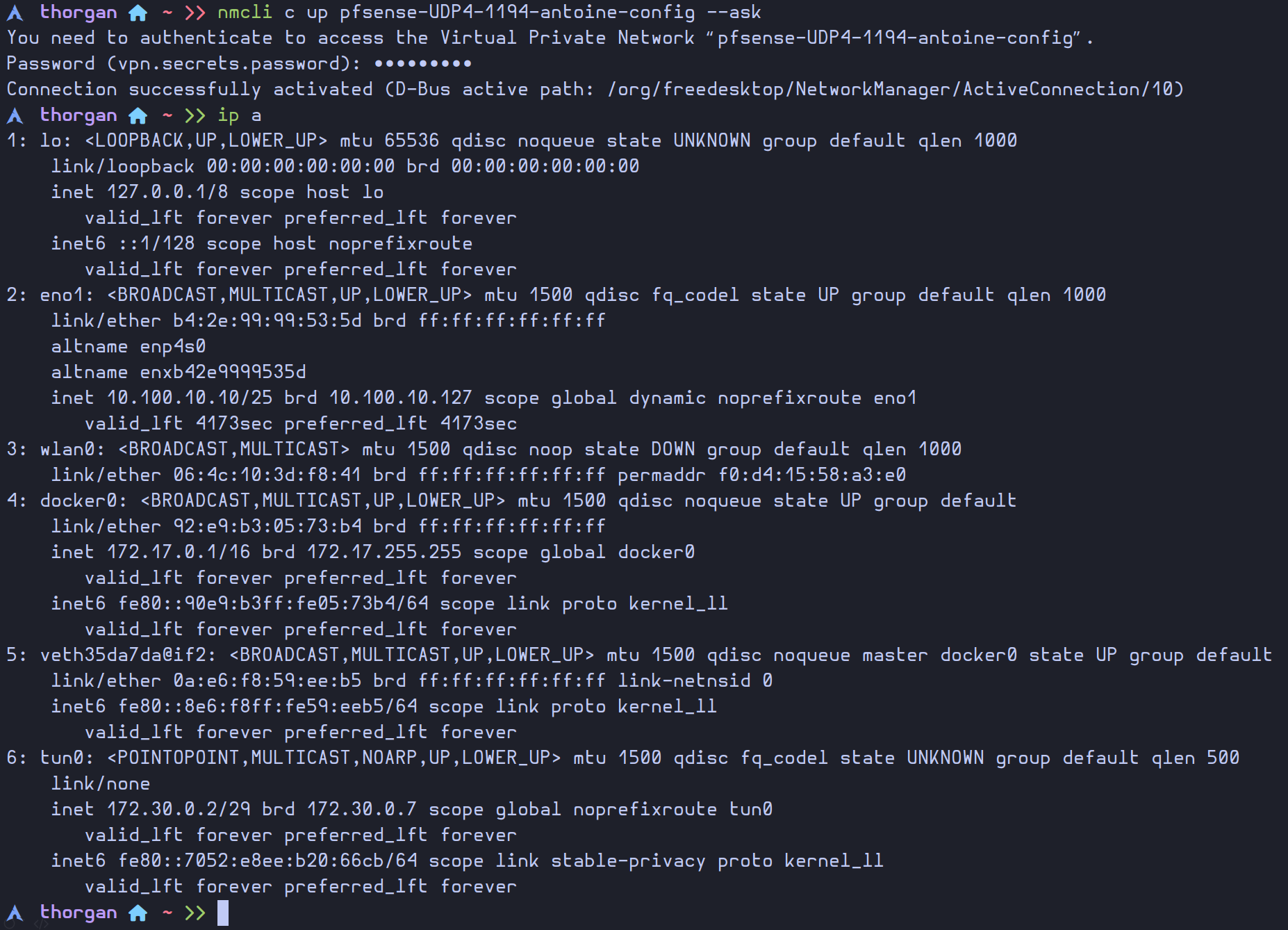
Now that the connection exists, we can easily use it with the command nmcli
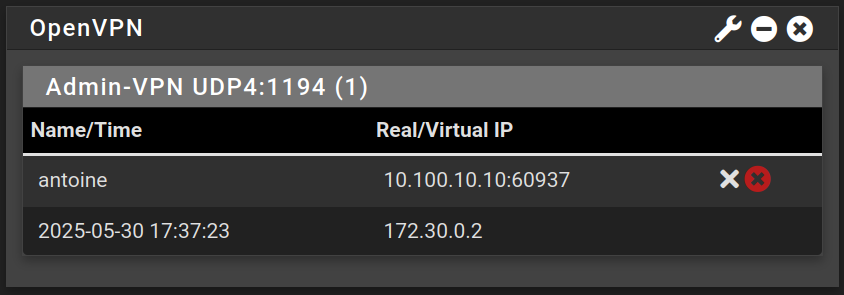
Now we can access the web configurator using the VPN, and we can see our current connection with the OpenVPN widget in the dashboard
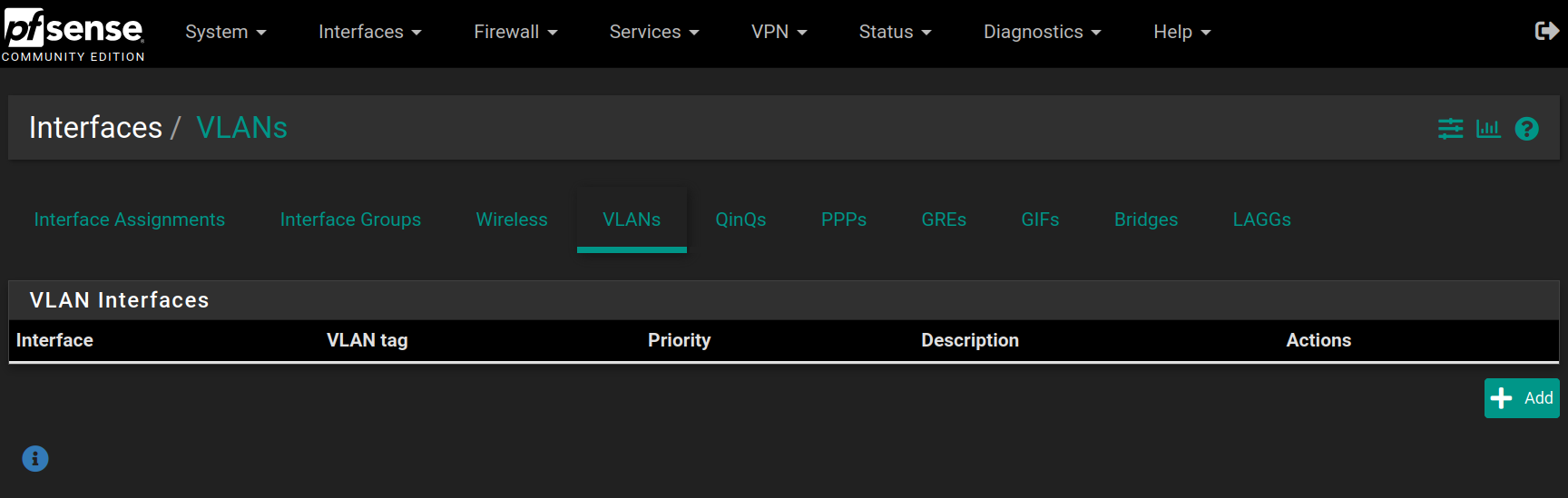
Go to Interfaces > Assignments > VLANs and click on Add
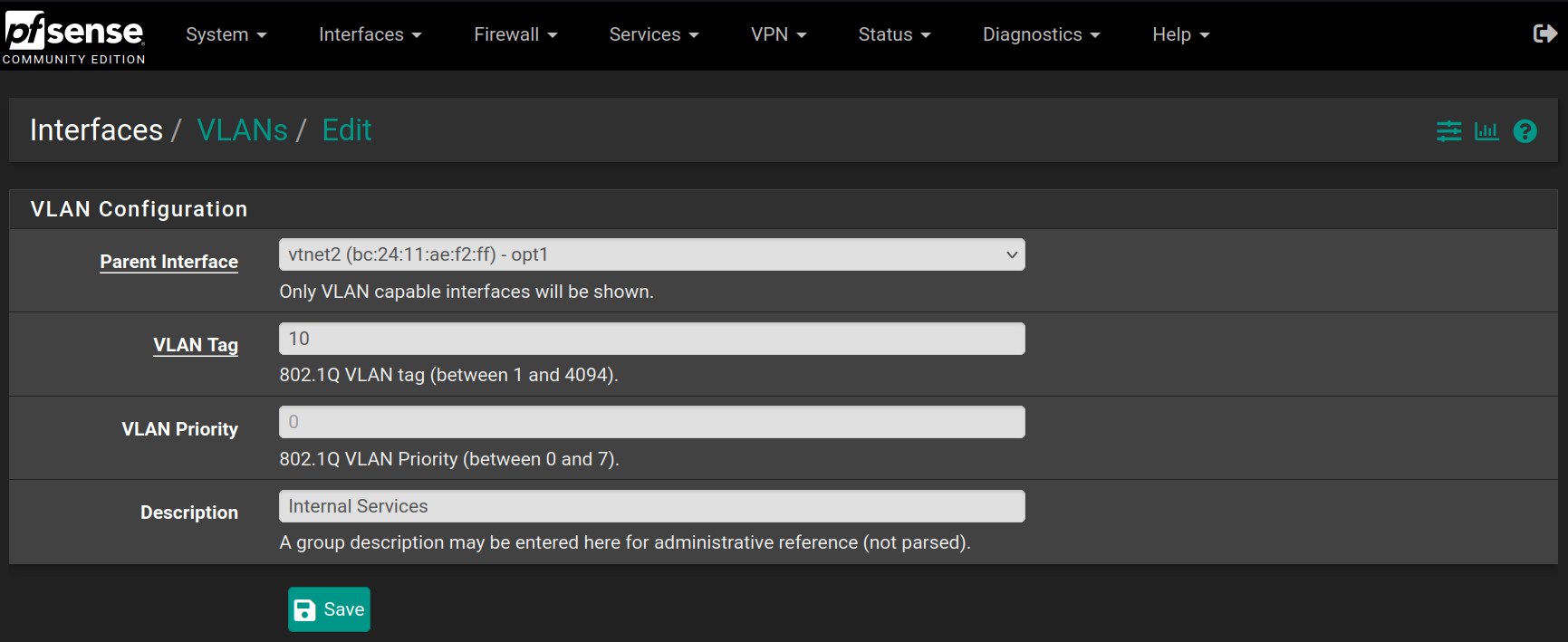
Choose the vtnet2 interface (OPT1) and set the VLAN at 10 describing it as Internal Services and click on Save
Then do the same for the Clients VLAN, with value 20 on the same network interface

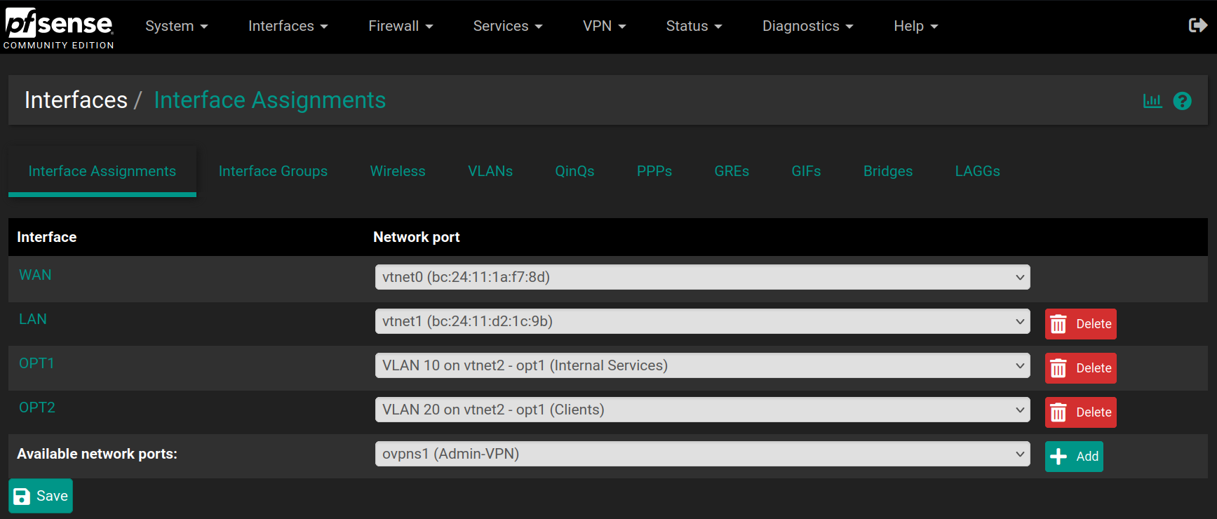
Go back to Interfaces > Assignments and set OPT1 as VLAN10 and add a new OPT2 as VLAN20 and click on Save
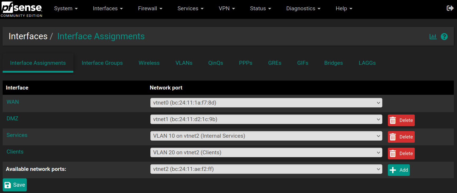
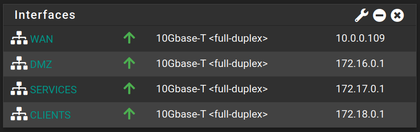
Then go to Interfaces > LAN, Interfaces > OPT1 and Interfaces > OPT2 to change their names with DMZ, Services and Clients, check the option Enable interface if it's not checked already and assign a Static IP address if it's not set up already.
| Interface | IP address |
|---|---|
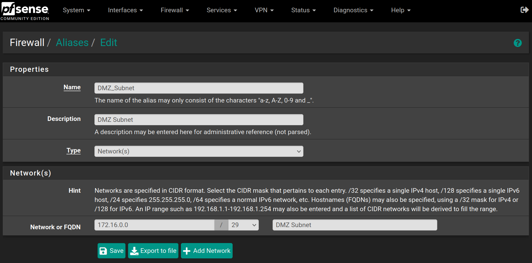
| DMZ | 172.16.0.1 / 29 |
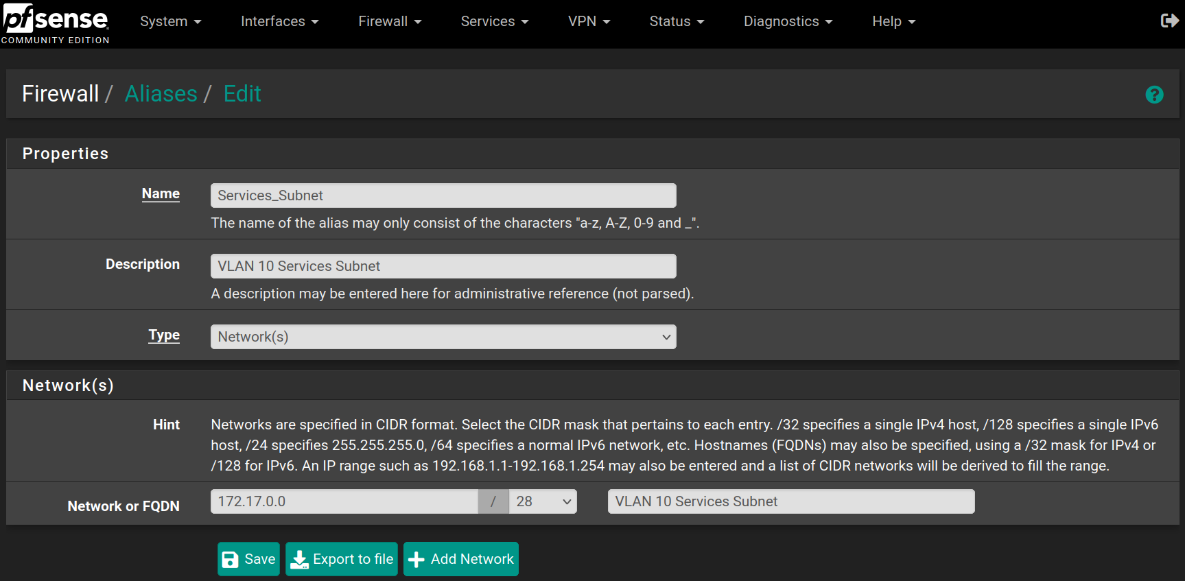
| Services (VLAN 10) | 172.17.0.1 / 28 |
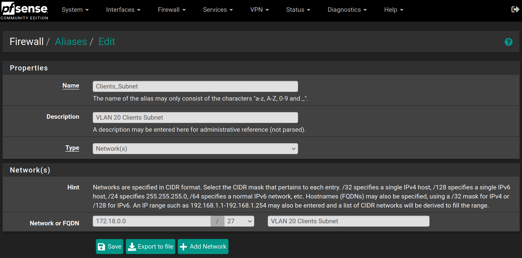
| Clients (VLAN 20) | 172.18.0.1 / 27 |
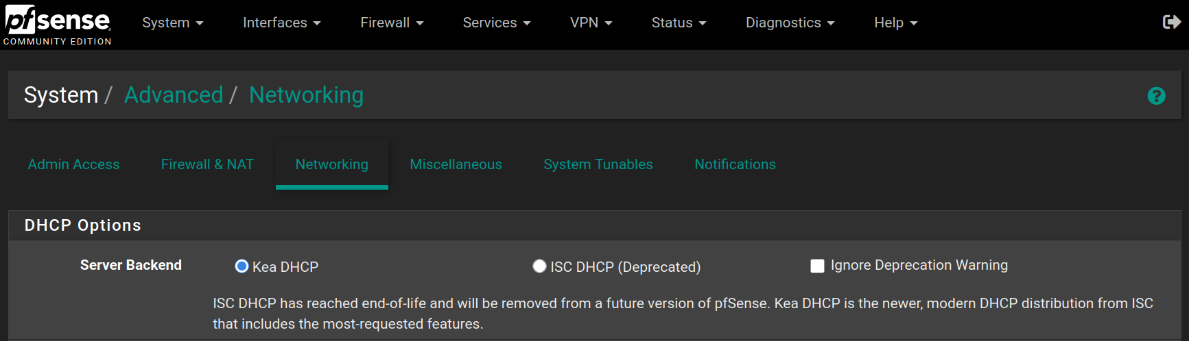
Go to System > Advanced > Networking to enable KEA DHCP instead of the deprecated ISC DHCP
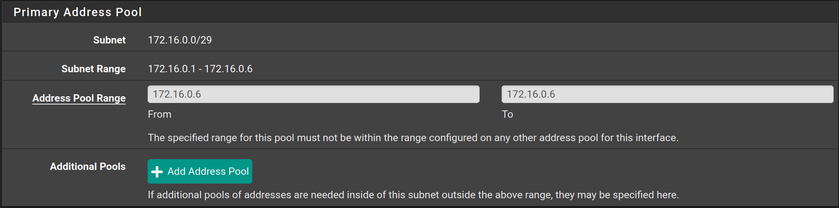
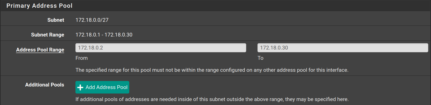
Go to Services > DHCP Server to configure the DHCP Server on each interface as following
| Interface | Starting IP | Ending IP |
|---|---|---|
| DMZ | 172.16.0.6 | 172.16.0.6 |
| Services | 172.17.0.14 | 172.17.0.14 |
| Clients | 172.18.0.2 | 172.18.0.30 |

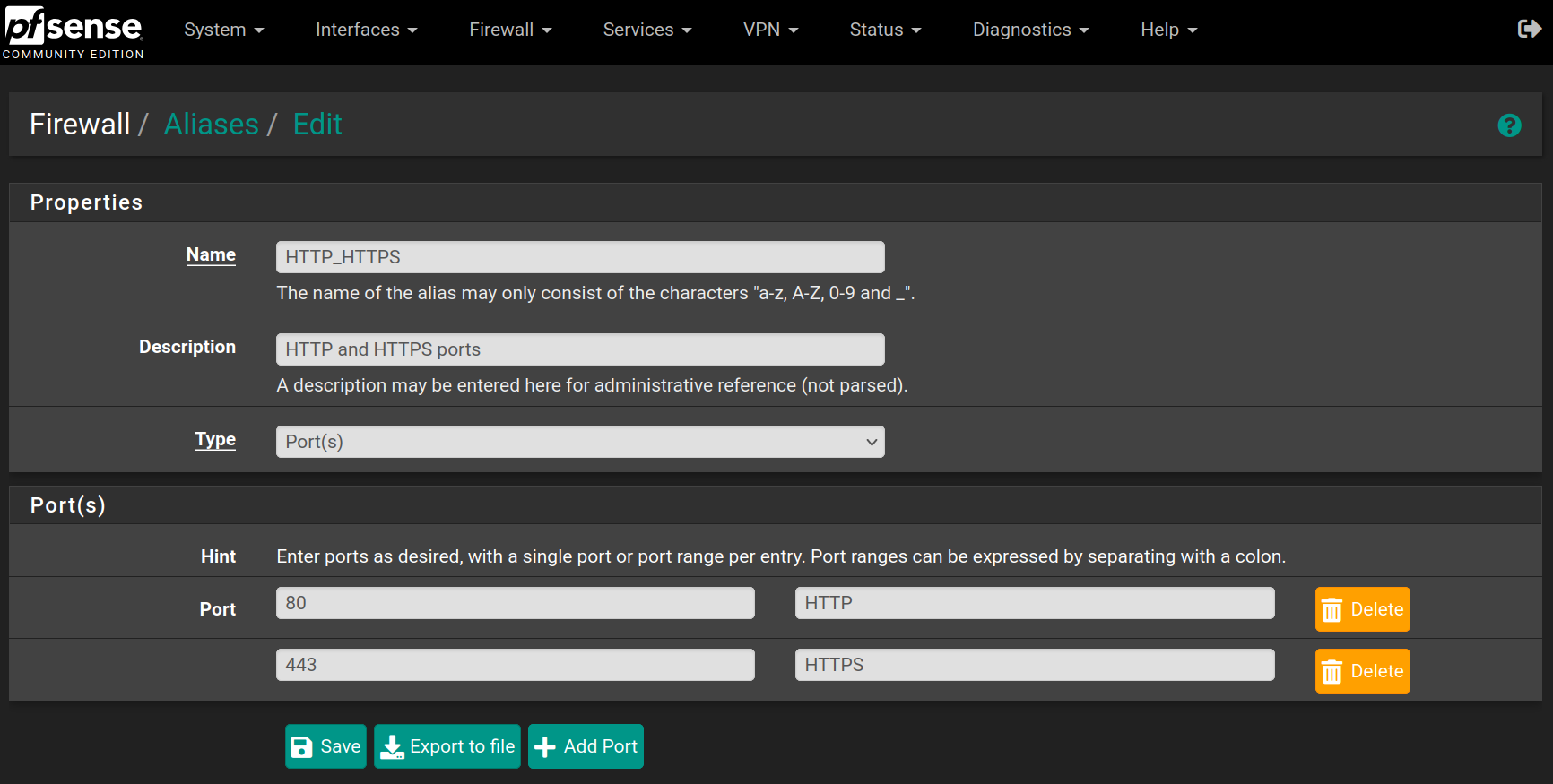
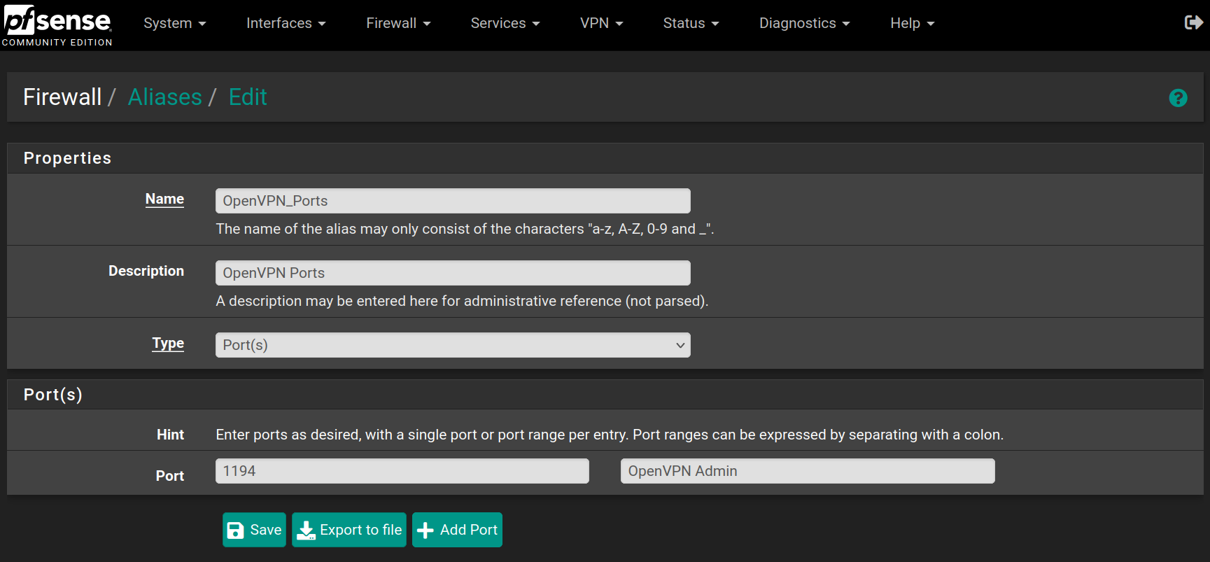
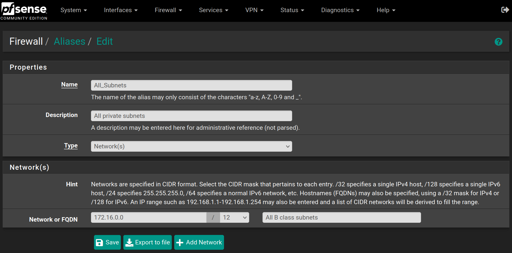
Create aliases
Go to Firewall > Aliases and click on New, then fill the forms with the values below and click on Save
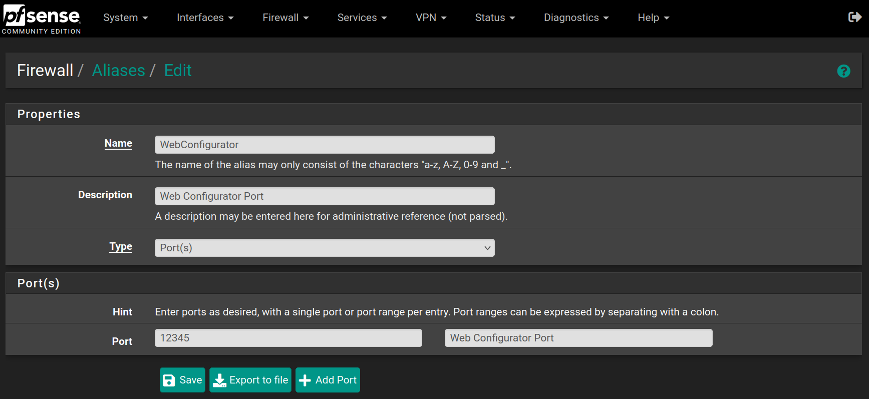
Repeat the process for the following aliases

No Comments